
Deduction of the Equations of the Chronometric Micrometer and Angular Micrometer
Introduction
In this article, I shall demonstrate how to deduce the equations that allow the calculation of the Angular Separation through measurements made with the Chronometric Micrometer (ref 1,2,3). Only one equations appear in the published literature of Astronomy, although strictly speaking, as we shall see, they are in reality four equations. I shall also present the steps that allowed me to arrive at the equations of the Angular Micrometer (ref 3) in 1991. However, I do not seek to present a rigorous mathematical treatise, but simply wish to explain how these formulas were obtained with the aide of the elementary tools of Algebra and Trigonometry.
Tools
We shall use the following trigonometric relationships:
- the sine rule: let "A" and "B" be certain angles, contained by two adjacent sides of a triangle, and let "a" and "b" be the opposed sides to these angles. then, in Plane Trigonometry, the sine rule presents the following form (see Fig 1):
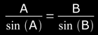 ( Eq 1 )
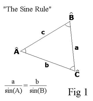
Let us remember that in reference to the sky we use only angles, not only to define the Position Angle (PA), but also for the Angular Separation (AS), although the AS expresses a longitude. but because the angle AS is extremely small, we can refer to the AS as if it were a straight line segment and, in consequence, as a first approach, we may use the Plane Trigonometry for our deductions from the Eq 1.
- Some definitions and trigonometrical equivalences, that the readers will easily recognize.
- Let us consider a eyepiece with a single wire or reticle line to facilitate the presentation.
Chronometric Micrometer
With the Chronometric Micrometer, the PA is measured by means of a protractor fixed to the focuser with a rotating eyepiece (wich has a wire (filament) or reticle line). A dial or pointer attached to the rotating eyepiece indicates the angles on the fixed protractor. On the other hand, to measure the AS, we must note the time that the two components of the binary system take to cross the wire (filament) of the reticle eyepiece with the drive motor off (see fig. 2).
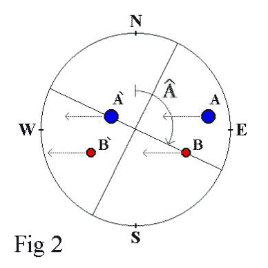
If we agree that "w" represents the apparent velocity of the celestial sphere, then we know that w =15.04"/sec approximately. If we consider an initial time t0=0 then, in a certain interval of time DT, DT=(t-t0)=(t-0)=t.
The sky describes a certain angle "a":
a = w . t
and in this way we can calculate the longitude of the arc traveled by a star with a certain declination "Dec":
q = w . t . cos(Dec) ( Eq 2 )
This is basically what it called Uniform Circular Movement in "Elementary Physics", considering that the velocity of the sky (in reference to the Earth) is constant, although at the present time it is known that this is not certain.
Now then, with a double star we can divide our problem into two parts:
MC1) PA=90° or PA=270°
MC2) PA different from 90° or PA different from 270°
Let us see:
MC1) : if the two components of the binary system have exactly the same Declination, they will move in the same direction or path (parallel to the Celestial Equator). the wire (filament) of the reticle eyepiece is located in N-S direction ; therefore, we can obtain the AS easily beginning with the Eq 2:
AS = w . t . cos(Dec) ( Eq 3 )
MC2) : if the two components of a double star system do not have the same Declination, they will move in different paths or direction. We should then rotate the wire (filament) of the reticle eyepiece to an angle "A" (angle that is measured the same as the PA), in order that the transit time of the pair is as long as possible.
There are two possibilities:
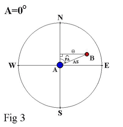
(1) A = 0°
The wire (filament) of the reticle eyepiece is rotated in the direction N-S, that is to say A=0°, then we simply need to solve the triangle presented in Fig 3:
From the Eq 2,
q = w . t .cos(Dec)
However,
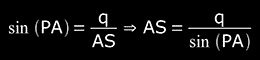
therefore, we replace the expression of q in the last equation and we arrive finally to:
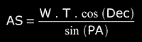 ( Eq 4 )
(2) A ≠ 0°
The wire (filament) of the reticle eyepiece is rotated to any angle. There are four possibilities, and each one corresponds a PA located in a different quadrant:
- 1st Quadrant, the situation is 0°≤PA<90°
- 2nd Quadrant, the situation is 90°<PA≤180°
- 3rd Quadrant, the situation is 180°<PA<270°
- 4th Quadrant, the situation is 270°<PA<360°
I) From Fig.4 we have the sine rule:
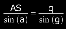 ( Eq(*) )
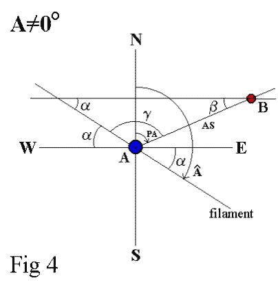
Let a = A-90° (Fig.4)
and because g = PA + (90°-a) (Fig.4)
we replace g = PA + (90°-(A-90°))
that is to say g = PA + (90°-A+90°)
g = PA - A + 180°
then, replacing the last expression of g and q in the Eq(*) we arrived at
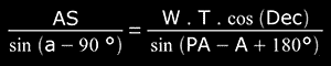
but sin(PA-A+180°) = sin(A-PA)
and sin(A-90°) = -(cos(A))
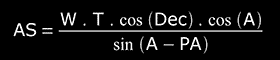
thereby, we finally arrive to:
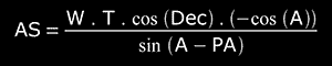
With procedures similar to the one described in (i), we obtain the other three equations. In order to save space, only the final results for each case are shown:
I)
( Eq 5 verified )
II)
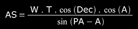 ( Eq 6 )
III)
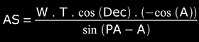 ( Eq 7 )
IV)
 ( Eq 8 )
Observations:
- the case MC2, where A=0°, is a particular case of anyone of the equations of mC2, where A≠0°.
- We can summarize these four equations by simply taking the absolute value of anyone of them.
Angular Micrometer
The main objective that I intended, when I devised the method of the Angular Micrometer in 1991, was that the AS be independent of the Declination of the binary system and the rotation of the Earth. If you wish the complete details of how the method of the Angular Micrometer was implemented, please consult reference 3.
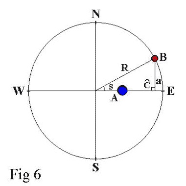
We can summarize the method of the Angular Micrometer by saying that the PA is obtained in the same way as with the Chronometric Micrometer. For the AS, on the other hand, using the protractor, another angle, called "S", should be measured. This consists of moving component A through the center of the field in either the E-W or N-S direction (according to the rules that I give in Table 3 on page 18 of my previous article in DSO #30, see ref. 3 ), until component B touches the border of the reticle eyepiece´s field (see fig. 6). We should also know with great precision the "Ratio of the field of the Telescope" (R), which is equal to half of the true field of view of the reticle eyepiece.
The process to find the final formula is divided into two stages, MA1 and MA2:
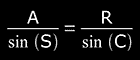
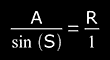
MA1) with component A in the center of the reticle eyepiece, we apply the sine rule to the triangle shown in Fig. 5:
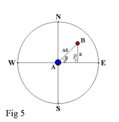
But C=90° , then sin(C)=sin(90°)=1, o sea sin(C)=1, and then
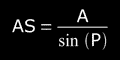
How do we obtain the value of side "a" ?, let us see the step MA2:
MA2) it is here where we use the "Angular Method": after measuring the PA of component B, which is in the 1st quadrant in our example, we rotate the wire or reticle line to the E-W (which is a function of the PA, as shown in Table 3 on page 18 of ref. 3), and we move component A along the E-W oriented wire or reticle line until component B touches the edge of the field of view (see fig.6). We now obtain a new triangle, shown if Fig. 6, to which we also apply the sine rule:
but angle C measures 90°, so sin(C)=sin(90°)=1, that is to say sin(C)=1.
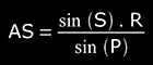
Therefore,
And we arrive at a = sin(S) . R
Replacing this last expression with the equation obtained in MA1), we finally arrive at:
 ( Eq 9 )
References
- Ronald C. Tanguay, "The Double Star Observer´s Handbook", 1998.
- William T. Geertsen, "Measurements of Double Stars Using the Chronometric Micrometer", Double Star Observer, Fall 1999 (Vol.5, Nº 4), pp. 9-15 ( DSO #19).
- Alejandro Eduardo Russo, "A New Visual Method of Measuring Binary Stars", Double Star Observer, May/June 2002 (Vol.8, Nº3), pp.13-19 (DSO #30).